New Draft ASME Standard for Additive Manufacturing Data Files

Example of defining a nonplanar, theoretical supplemental surface on a 3D-printed part. This is useful so that designers can designate manufacturing tolerance zone relative to that surface. (Image reprinted from ASME Y14.46-2017, ibid)


Latest News
February 23, 2018
CAD-generated drawings include clearly marked dimensions, tolerances and annotations, providing essential directions for manufacturing. So far, such clarity has been lacking in the world of additive manufacturing (AM/3D printing) without extensive notations added by individual users or perhaps listed according to each company’s internal standards.
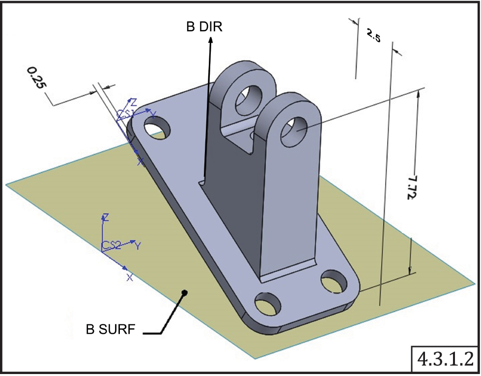 Example of defining the orientation of an additively manufactured part relative to the build surface (B SURF). The build direction is shown as B DIR. (All images reprinted from ASME Y14.46-2017 (Draft Standard for Trial Use), by permission of The American Society of Mechanical Engineers. All rights reserved.)
Given the shape-only information saved in the commonly used STL file-format, designers need additional and better ways to convey important build information. Is there a required build direction that’s critical to designate? How do you define material gradients and colors, if available? Where do you specify which sections of a part need different surface textures or porosity? And are there regions of a part where you don’t want any support structures attached?
Y14 Standards to the Rescue
Dozens of subject matter experts within the American Society of Mechanical Engineers (ASME) have been tackling these questions and more, in an effort that formally began in October 2014. The Y14.46 Subcommittee was chartered with creating “a broadly accepted standard that incorporates, expands, or refines international practices and symbology to enable AM product definition data sets to be created, interpreted, and consumed on a global basis.”The draft standard, published on Nov. 15, 2017 and termed Y14.46-2017, “extends the ASME Y14 series of standards to leverage model-based product definitions for additive manufacturing.” Its title is “Product Definition for Additive Manufacturing” and its goal is to improve manufacturing efficiency with precise methods of controlling product definition. The key is doing this directly in the model.
ASME expects the new standard, when approved, will greatly help anyone involved in mechanical design, drafting, quality assurance and supply-chain management working with additively manufactured parts and assemblies.
AM Model Specification Sub-Topics
Once you get past the general-sounding project scope – “definitions of terms and features unique to additive manufacturing technologies with recommendations for their uniform specification in product definition data sets and in related documents” – the value of its detailed content becomes apparent.Beginning with the section called Supplemental Geometry, the standard calls out the often critically important concepts (for AM parts) of identifying the required build direction, gravity direction, build surface (which may or may not be planar with the part), and theoretical supplemental surfaces. The latter becomes necessary for defining a tolerance zone at an outer surface or inner region, so that the as-designed dimensions can be compared with those as-built. An example of such a surface in use would be the set of points where a lattice structure defines a non-solid, effective surface – again, this can be flat or non-planar.
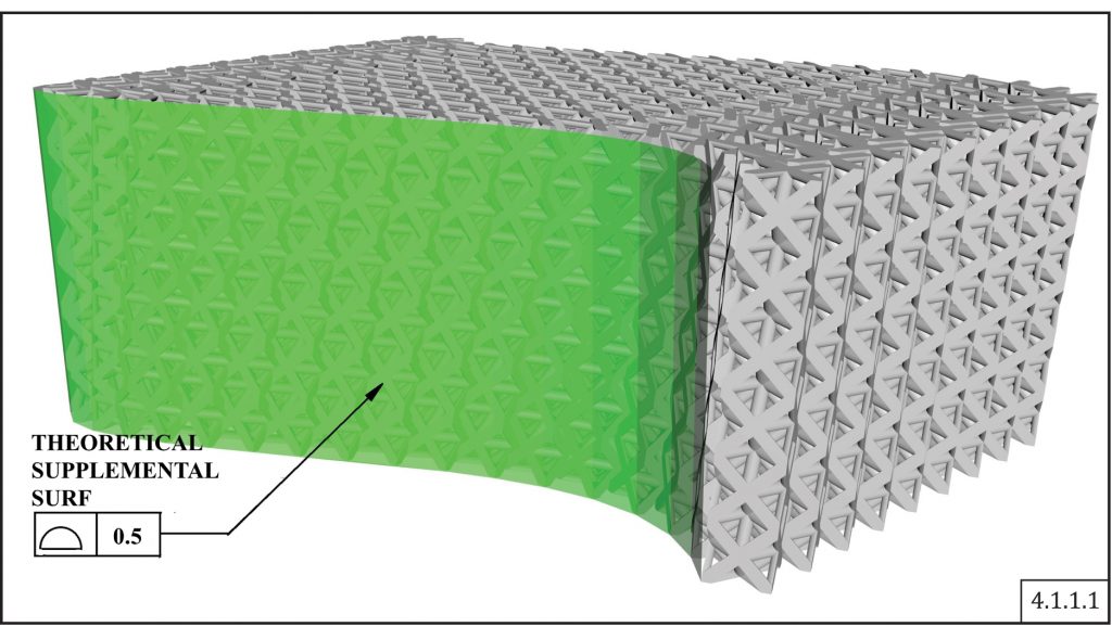 Example of defining a nonplanar, theoretical supplemental surface on a 3D-printed part. This is useful so that designers can designate a manufacturing tolerance zone relative to that surface. (Image reprinted from ASME Y14.46-2017, ibid)
The next section, Product and Process Definition Requirements, addresses many aspects of defining both the design (such as specifying different surface tolerances in different regions of a part) and the process (e.g., for a laser-sintered part, note if it’s important to build the part in the center of the build platform to minimize laser-spot ellipticity or thermal variations). The model definitions can even specify leaving a “no build” zone around a part when it is nested within a multi-part build.
Under Process-Related Characteristics, layer thickness, tracing path, fill patterns and support structures are all addressed. Since support structures play a key role in producing an acceptable part, there’s quite a bit of guidance about identifying where supports are required, where they’re not allowed, and what percentage coverage is needed. Another sub-section demonstrates how to specify the location and orientation of test coupons.
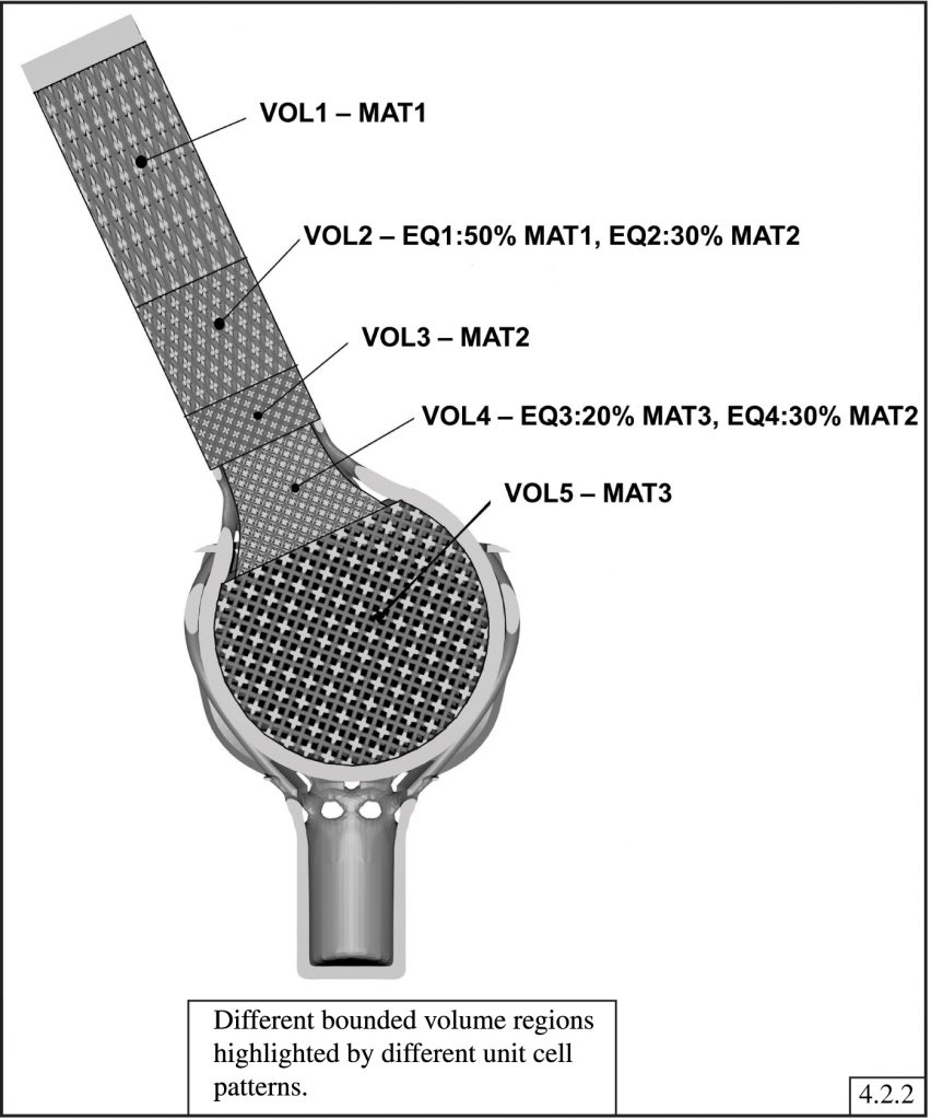 Proposed material transition specification in an additively manufactured part, identifying bounded volume regions with different lattice infills. VOL2 is the transition region between material MAT1 in VOL1 and material MAT2 in VOL3. (Image reprinted from ASME Y14.46-2017, ibid)
Lastly, the document establishes model-based (as opposed to drawing-centric) data-package requirements for each stage of AM production: Design, Build, Post-process (required/optional), and End-product Inspections (required/optional). Metadata can include specifying the exact AM process such as material extrusion or binder jetting, or a “joining mechanism” such as laser or electron beam.
Still to Come – Forward Work
Two sections of the document (Complex Geometry and Design for Assembly) are introduced but not yet filled in; work in these areas is ongoing and the committee encourages user input beyond — or in addition to — comments on the existing information.Kudos to ASME and its Y14.46 Subcommittee for taking on this tedious but important task. When it is finally approved by the American National Standards Institute (ANSI) it will have wide-reaching, positive impacts in spreading effective, consistent use of AM production technologies.
ASME Y14.46-2017 can be ordered by downloading a digital PDF ($50 US). During the one-year trial and comment period (ending November 2018), interested parties may submit suggestions for revision using the Comment Form which automatically downloads a Word document to be filled out and emailed to committee member Remington Richmond.
Subscribe to our FREE magazine, FREE email newsletters or both!
Latest News
About the Author
Pamela Waterman worked as Digital Engineering’s contributing editor for two decades. Contact her via .(JavaScript must be enabled to view this email address).
Follow DE

