3D-Printed Rocket Engine Launches New Company
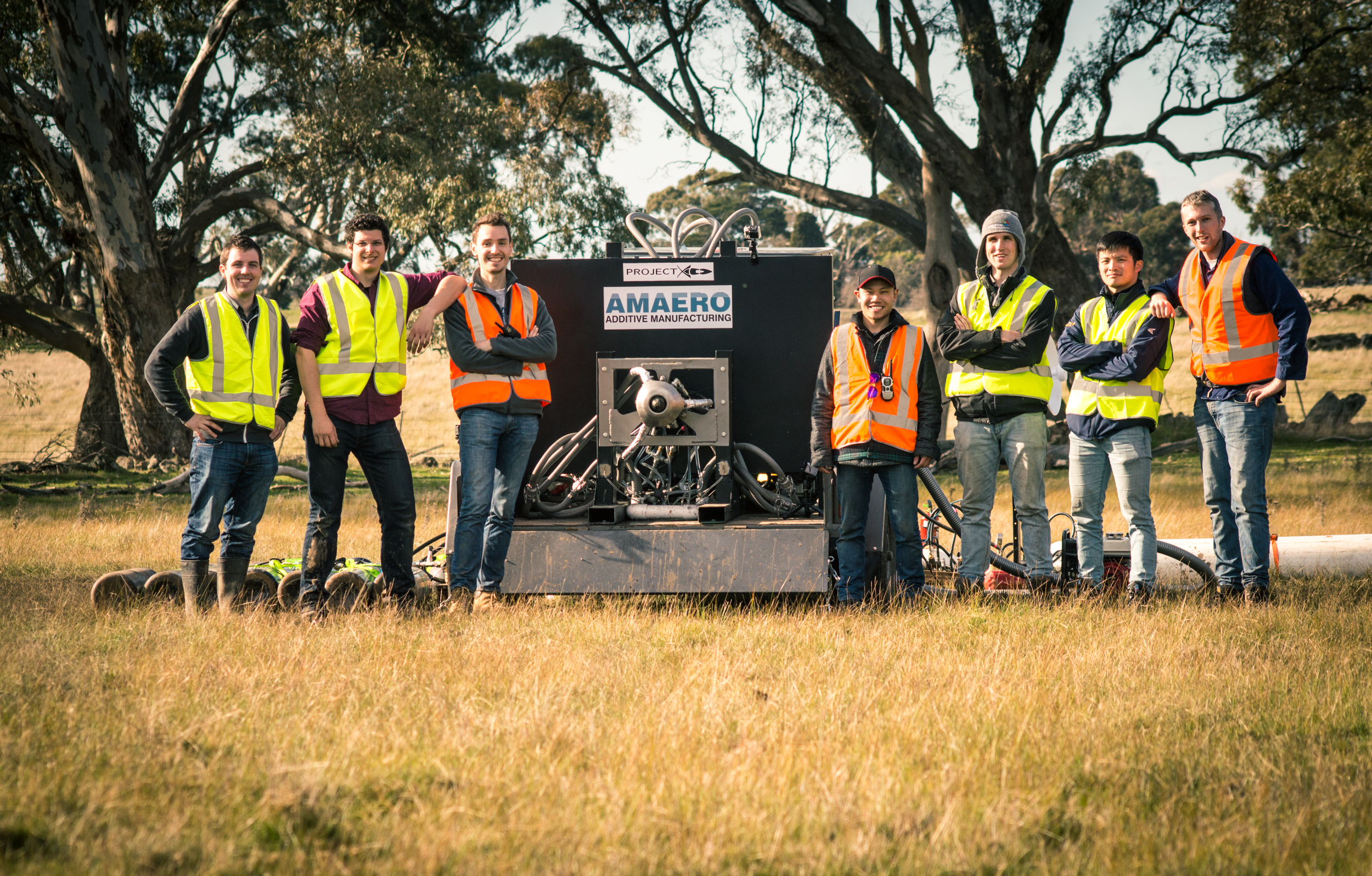
Design team from AMAERO and Monash University, both in Australia, with their efficient aerospike rocket engine. The engine was 3D-printed in just two parts on an EOS 280 metal AM system. (Image courtesy AMAERO)


October 10, 2017
Rocket science has been a cool subject since Robert Goddard demonstrated his experiments in the 1920s. 3D-printing/additive manufacturing (AM) is a bit newer technology (usually pegged to 3D Systems’ 1987 commercialization of stereolithography apparatus (SLA)) but is equally cool in a hundred different ways. Put them together and you have the potential to shoot for the moon, planets, stars and more. Recently two engineering groups on opposite sides of our planet took the first steps to do just that.
Three, Two, One, Ignition
Every time you join two or more parts in an assembly, you spend time and money on labor. In addition, for components that require brazing two very different types of metal (in a process similar to soldering), the joint region could be susceptible to mechanical failure. Engineers at NASA Marshall Space Flight Center in Huntsville, AL, are using 3D-printing technology to eliminate these issues in a prototype rocket engine igniter made from Inconel 625 and C18150, a copper chromium zirconium alloy.Previously, the 10-in. tall by 7-in. diameter igniter was built by brazing and welding together four separate parts. This time, the component was created during a single build run on a DMG MORI hybrid AM system — equipment that integrates traditional CNC machining capabilities with a blown-powder laser deposition process.
Led by senior engineer Robin Osborne of ERC (Huntsville), the Marshall test-team conducted 33 test runs, all of them 5 seconds long except for one 10-second test. “The conditions simulated low pressure, transient start-up ignition conditions for a liquid propellant rocket engine,“Osborne says.“Because we tested a range of start-up conditions, the igniter experienced transient temperatures ranging anywhere from -250°F to 2200°F.”
Not only did the 3D-printed igniter fire successfully each time, it displayed improved mechanical properties compared to the traditionally brazed version. Researchers at the University of Alabama examined cross-cut slices of the igniter and saw that the Inconel and copper alloy had interdiffused, creating a strong bond without a sharp transition.
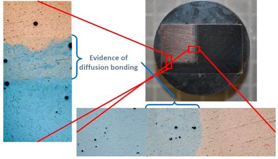 Section of bimetallic rocket-engine igniter, built on a DMG MORI hybrid additive manufacturing system for NASA Marshall Space Flight Center. Microscope image shows diffused interface region between the two metals (Inconel 625 and copper C18150). (Image courtesy NASA)
“By diffusing the two materials together through this process,” says Majid Babai, advanced manufacturing chief and lead for the project in Marshall’s Materials and Processes Laboratory, “a bond is generated internally with the two materials, and any hard transitions is eliminated that could cause the component to crack under the enormous forces and temperature gradient of space travel.”
The new, hybrid technology will also allow much larger and more complex parts to be made, since it permits access to internal areas for in-process machining. “This process could reduce future rocket engine costs by up to a third and manufacturing time by 50%,” says Preston Jones, director of the Engineering Directorate at Marshall.
3D-Printed Rocket Engine Improves Efficiency
Any time you witness a rocket launch, live or on TV, you see the classic bell-shape structures that flare out from the base to guide the exhaust. This geometry makes the engines produce peak-efficiency thrust at ground level and in the instant of launch; however, as the rocket climbs the decreasing atmospheric pressure causes the exhaust to spread out, reducing thrust. Yet for decades, this has represented the best (i.e., most manufacturable and functional) available design.Acknowledging these limitations, engineers have spent decades working on variations of a very different concept: a configuration based on a central aerospike (sometimes called an inside-out rocket engine).
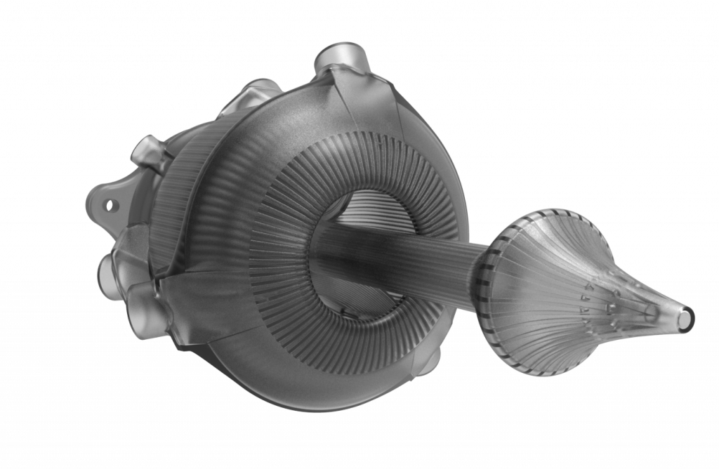 Aerospike-design rocket engine additively manufactured in just two pieces on an EOS M280 DMLS system. Designed by AMAERO, it maintains efficient thrust with increasing altitude/decreasing atmospheric pressure. (Image courtesy AMAERO)
This nozzle shape takes full advantage of the changing atmospheric pressure as the rocket advances in altitude. In this design, exhaust gases shoot directly down along a narrow central spike, hugging it concentrically at ground level then increasingly expanding outwards as the rocket rises and external pressure decreases. The gases form their own bell shape, producing optimum thrust at any altitude.
Two difficulties have prevented the use of this general design: manufacturing the internal spike support structure and carrying away the heat built up inside of the spike. Now, a team of designers from Australia’s Monash University and a spin-off company called AMAERO (founded in 2013) have successfully demonstrated such an engine by 3D printing it.
Test-Firing an 3D-Printed Rocket Engine
Marten Jurg, an engineer with AMAERO, explains that the engine was built in two sections on an EOS M 280 metal laser sintering AM system, virtually filling the build volume. “The mounts were up to 240mm across and the aerospike was just over 300mm long,” says Jurg. “This was very intentional, as we wanted to maximize the thrust able to be produced by the engine.” The company also operates even larger metal AM systems from Concept Laser and Trumpf, and works with multi-material deposition.For the aerospike design, creating the engine in two pieces allowed the AMAERO team to access and machine a portion of the critical flow surfaces. “The entire engine was designed with AM in mind, knowing the material (Hasteloy X, a nickel-based super alloy) and the process limitations,” Jurg says. “In the engine, we had features down to 0.5mm thick, and with our enhanced processing parameters, were able to print threads that required minimal post-processing before use.”
 Rocket plume from 3D-printed aerospike-design demonstrator engine, during static testing. (Image courtesy AMAERO)
To address overheating, the combustion chamber piece integrated all injectors and manifolds with subsurface conformal cooling channels. “That is one of the key advantages of AM,” Jurg points out. “Combining all of these features (with traditional processes) would typically require hundreds of hours of assembly or machining.” See videos of the rocket being 3D-printed and test fired below.
This project was a challenge by AMAERO to Monash University students to demonstrate the geometric complexities possible with AM technology. The Ph.D. students involved have now created their own company, NextAero, and plan to offer such concepts to the global aerospace industry.
Subscribe to our FREE magazine, FREE email newsletters or both!
About the Author
Pamela Waterman worked as Digital Engineering’s contributing editor for two decades. Contact her via .(JavaScript must be enabled to view this email address).
Follow DE

